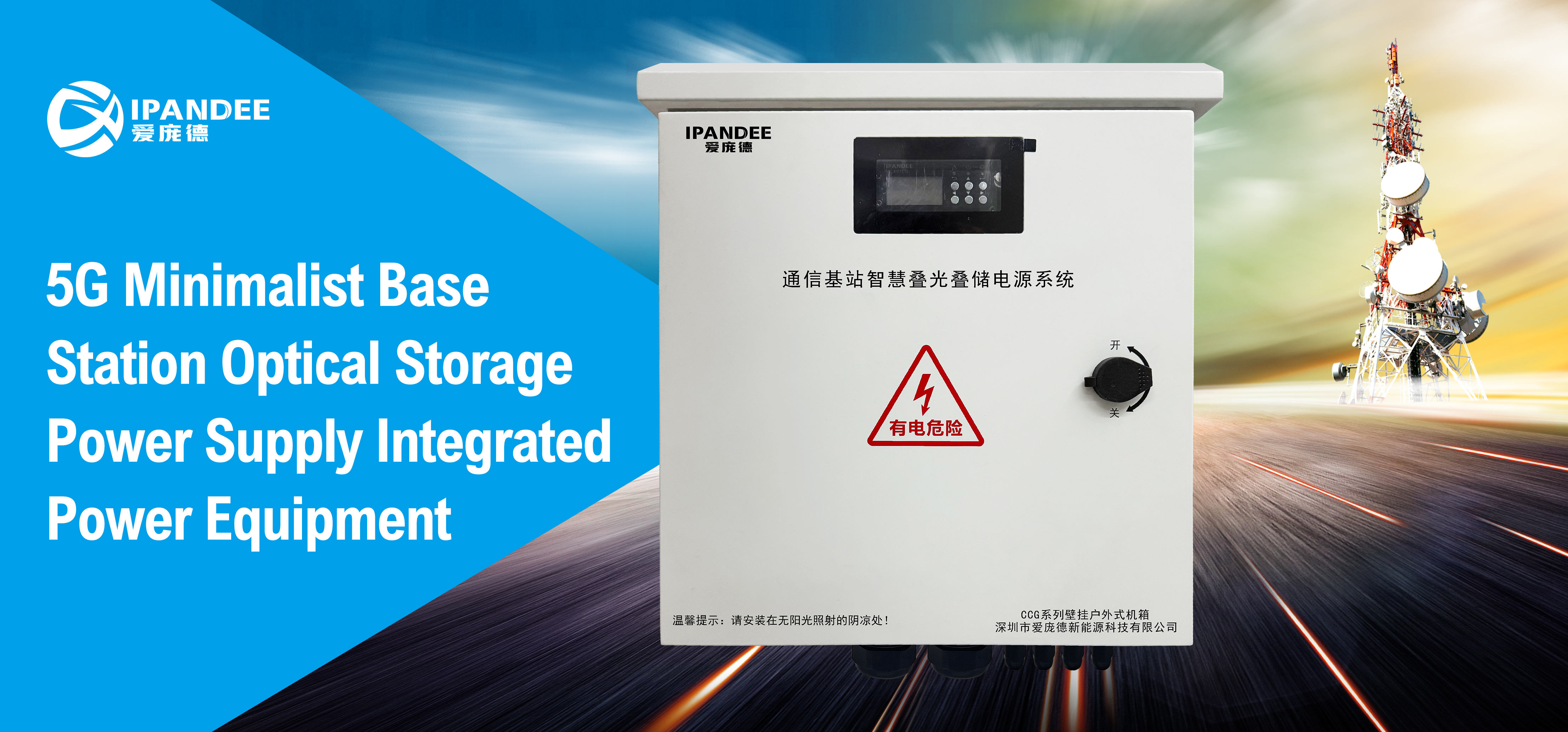
In order to protect the battery and prevent overcharging, most solar power systems include a charging controller. Its basic function is to cut off the charging current when the battery is full. Since different batteries have different charging characteristics, the charging controller should be selected according to the type of battery. Today we will introduce the classification of solar charging controllers.
According to the different principles of the controller's regulation of battery charging, commonly used charging controllers can be divided into:
Introduction of series-connected solar charging controllers
A switch element is connected in series between the photovoltaic module and the battery. The control detector circuit monitors the battery terminal voltage. When the charging voltage exceeds the full charge disconnection value (HVD) set by the battery, the switching element cuts off the battery charging circuit and resumes battery charging.
The series-connected charging controller can use a relay as a quick switch. At present, power field-effect transistors (MOSFETs), IGBTs, solid-state relays are mostly used. The switching element in a well-designed series-connected charging controller can also replace the anti-reverse diode, which plays a role in preventing "reverse leakage" at night.
Since the control switching element is connected in series in the charging circuit, the voltage loss of the circuit is relatively large, which reduces the charging efficiency. In addition, when the switching element is disconnected, the input voltage will rise to the level of the open-circuit voltage of the power generation unit. Therefore, when designing a series-connected charging controller, low-pass state MOSFETs and low-saturation voltage drop IGBTs should be selected.
Introduction of parallel-connected solar charging controllers
The switching element of the parallel-connected charging controller is connected in parallel at the two ends of the photovoltaic module, so it can solve the power loss problem of the switching element in the series-connected charging controller.
The controller detection circuit monitors the battery terminal voltage. When the charging voltage exceeds the full charge disconnection value (HVD) set by the battery, the switching element is turned on to bypass the battery.
When the battery terminal voltage drops to the set battery recovery charging voltage value, the switching element is disconnected, and the battery charging circuit is turned on at the same time.
The input circuit of the parallel-connected solar charging controller usually has a diode, which can allow current to flow into the battery during charging and prevent battery current from flowing to the photovoltaic array at night or on cloudy days. The parallel-connected charging controller has a simple circuit, is cheap, but when the battery is full and protected while the photovoltaic array is still generating power, it will generate a large short-circuit current, create a "hot spot", accelerate aging, and is not recommended.
Introduction of PWM-type solar charging controllers
In order to effectively prevent overcharging and make full use of solar energy for battery charging, pulse-width modulation (PWM) charging controllers have been developed in recent years. The PWM charging controller switches the input of the photovoltaic module in a pulsed manner. When the battery tends to be full, as its terminal voltage gradually increases, the frequency or duty cycle of the pulse changes, shortening the conduction time and gradually reducing the charging current.
When the battery voltage drops below the full charge point, the charging current will gradually increase again. This charging process forms a more complete charging state, which can increase the total cycle life of the battery in the photovoltaic system. The charging status of the PWM charge protection can increase the total cycle life of the battery in the photovoltaic system.
The PWM charging protection circuit is mainly parallel-connected protection circuit. Using this type of circuit has the advantages of both protecting the battery and making full use of energy. In addition, PWM solar charging controllers can also achieve maximum power tracking function for photovoltaic systems. Therefore, pulse-width modulation controllers are also commonly used in large-scale photovoltaic systems. The disadvantage is that the PWM modulation controller itself brings a certain switching loss (about 4% to 8%).
 English
  한국어
한국어  français
  Deutsch
  Español
  italiano
  русский
  português
  العربية
  tiếng việt
  ไทย
ไทย  Polska
  中文
中文


